Minimum Drilling and Tapping Depths for Limited Material Thickness
The KATO Tech Group frequently receives inquiries asking if it is possible to decrease the drilling and tapping depths detailed in NASM33537 (formerly MS33537) because of limited material thickness or other reasons. Obviously one solution is to select a shorter insert length, but this isn’t always possible. Another solution is to modify the drilling and tapping depths and insert setdown.
The drilling and tapping depths are calculated based on the style of tap being used. For example, most STI Plug style taps have a 4-pitch thread chamfer, and bottoming taps have a 2-pitch thread chamfer. These partial threads must be allowed for at the bottom of a blind hole. Another consideration is countersinking. Good machining practice dictates that a countersink be provided at the top of the tapped hole. Countersinking is recommended before tapping to create a good starting thread. The average depth of the countersink is ½ pitch. Insert setdown with a countersink is ¾ to 1-½ pitches below the top surface of the tapped hole.
Another important concept to understand before we get into specific examples is insert length. The Nominal Length (LNOM) cannot be measured in the free state. It is a calculated value equal to the Assembled Length (LA) plus ½ pitch. The assembled length of an insert (LA) has a tolerance of (+0, –1/4 P).
Definitions:
- F = Drill Depth (to lip of drill)
- H = Full Thread Tapping Depth
- P = Pitch in Inches = 1/ (Threads per Inch)
- LA = Insert Assembled Length = LN – (1/2 P)
Figure 1 shows a ½-20 x .500 long insert installed to the maximum setdown depth of 1-½ pitches (threads) below the top surface, with a countersink. The minimum full thread tapping depth (H) for through and blind holes is equal to the insert nominal length (LN) plus one thread pitch. In this case H = .500 + .050 = 0.550.
The magnetic permeability of a standard free-running insert usually falls between 2.0 and 10.0 G/O. The variation is due to the different lengths and wire sizes.
Usually locking type inserts have a slightly higher G/O value due to the additional work hardening that results from the formation of the locking coil. This is exciting stuff – right?
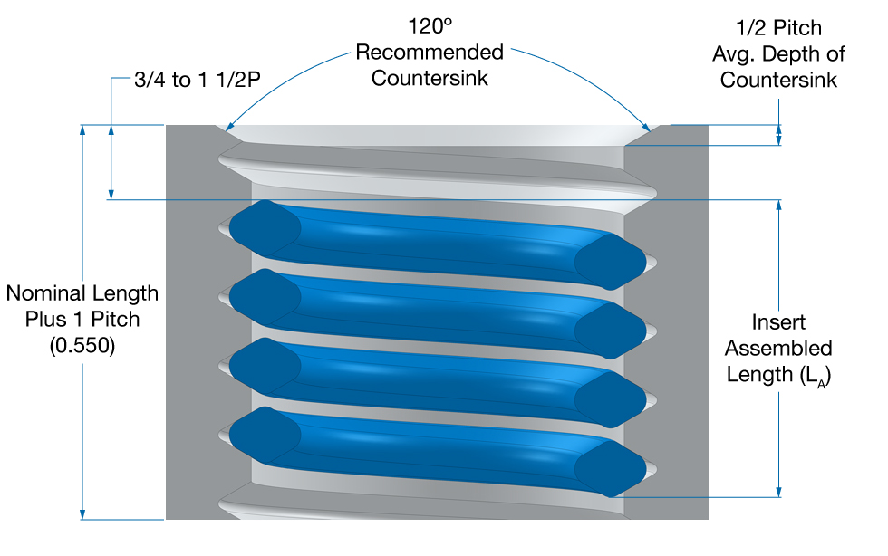
Figure 1: 1/2-20 X 0.500 (1 Dia.) with Countersink
Example: ½ -20 x 1 Dia. (.500) Length Insert, Plug Tap, With Countersink, and Setdown ¾ to 1-½ pitches below surface.
FMIN = LA+ Set Down + Tap Chamfer Length + Drill Clearance + Tap Male Center Length*
- KATO Plug Taps 5/16 and smaller have a male center with an average length that is equal to ½ (LNOM). In this case, it is
not necessary to allow for this. Drill clearance is typically 1 full thread
P = 1/20 = .050in.
LA= LN– (1/2 P) = .500 – ½(.050) = 0.475
FMIN = .475+1.5(.050)+4(.050)+1(0.50)
HMIN = LA + Set Down = .475 + 1.5(.050)= 0.550
Figure 2 shows a ½-20 x .500 long insert installed to the maximum setdown depth of ½ pitch (thread) below the top surface without a countersink. The minimum full thread tapping depth (H) for through and blind holes (without a countersink) is equal to the insert nominal length (LN). In this case H = LN = .500.
For limited material thickness, you can decrease the drilling and tapping depths and do one or more of following and still accommodate the full insert length and set it below the top surface:
- Remove Tap Male Center (sizes 5/16 and smaller) reduces the drilling depth by ½ the nominal diameter of the thread.)
- Change Tap style for Plug to Bottoming saves and average of 2 threads.
- Eliminate Countersink saves an average of ½ thread.
- Reduce Insert Setdown to ¼ to ½ pitch below surface (maintain ¼ pitch tolerance) will save ½ thread pitch (without countersink).
In addition to steps 1 through 4, special drills can be used with decreased drill point angles, or by the use of flat bottom drills.
Standard drills have a 118° Drill Point Angle. The length of the (standard) Drill Point can be calculated using the following:
LDrill Point =(Drill Diameter) x 0.6
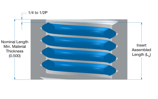
Figure 2: 1/2-20 X 0.500 (1 Dia.) without Countersink
Example: ½ -20 x 1 Dia. (.500) Length Insert, Bottoming Tap, Without Countersink, and Setdown ¼ to ½ pitch below surface.
FMIN = LA + Set Down + Tap Chamfer Length + Drill Clearance
= .475 + 0.5(.050) + 2(.050) + 1(.050)
= 0.650
HMIN =LA + Set Down = .475 + 1.5(.050) = 0.500
Well this was exciting reading, wasn’t it? Believe it or not, we do receive questions on this all of the time, because designers being concerned with space and weight savings do not always allow adequate material thickness for the machining and assembly people to work with. So, hopefully this will be helpful to those of you who have a need to explore this subject.
If you have any questions, please contact us.
For more technical articles, register to KATOpedia today! Registration is FREE, and take less than 1 minute to complete and gain access to the world's most comprehensive online encyclopedia for helically coiled screw thread inserts and tools.